Experimental Study on the Stress Variation of Concrete Containing F-fiber Extracted from Waste FRP
Even though to discard the waste FRP (Fiber-Reinforced Plastic) is urgent and problematic, the way to do it has not been efficient. In our project team the FRP have been splitted into some layers which have different physical properties; mat and roving layers. Among those, the roving layer woven like a basket by bundles of glass fibers has been cut into reusable fibers called ‘F-fiber’. F-fiber is 1 mm or 3 mm in width and 3 cm in length. It is used in fiber-reinforced concrete (FRC) with 0.5%, 0.7%, 1.0%, or 1.5% of volume ratio. Produced FRC was tested in compressive, tensile, and bending stress in contrast to the without-fiber (standard) concrete and 0.1% polypropylene reinforced concrete (PP-FRC). The tensile and bending stresses are more or less those of PP-FRC. The compressive stress, however, is similar (with 3 mm F-fiber) to or lower (with 1 mm F-fiber) than that of standard concrete. Conclusively the usage of the waste FRC in concrete is advised to be limited to the one where the compressive stress is not much critical.
초록
폐 FRP의 처리는 매우 급박하나 뚜렷한 생산성 있는 방법이 많지 않다. 본 연구진은 FRP의 층간 구성에 초점을 맞춰 층으로 분리하였으며, 각 층의 구성 성분에 따라 물성이 다름을 확인한 바 있다. 그 중 유리섬유 다발이 바구니 조직으로 틀을 이루고 있는 로빙층에서 유리섬유(“F섬유”)를 제작하였다. 그 크기를 폭 1 mm와 3 mm로 달리하고 길이는 3 cm로 잘라 부피비로 0.5%, 0.7%, 1.0%, 1.5%를 포함하도록 섬유강화 콘크리트(fiber reinforced concrete, FRC)를 제작하였다. 압축강도, 인장강도, 휨강도를 비교하기 위해 강화재를 포함하지 않은 것과 합성수지(polypropylene, PP)를 0.1% 포함하는 비교 샘플도 제작하였다. 실험결과 인장강도와 휨강도는 PP를 포함하는 것과 유사하거나 버금가는 강도를 보인 반면, 압축강도는 강화재를 넣지 않은 것과 유사하거나(3 mm 폭), 약 20% 정도 감소하였다(1 mm 폭). 이 결과를 바탕으로 폐 FRP소재를 건축자재로 쓸 경우에는 압축강도가 큰 영향을 주지 않는 부분에 사용할 것을 권한다.
Keywords:
F-fiber, Fiber Reinforced Concrete, Compressive Stress, Additive Composite Material, F섬유, 섬유강화 콘크리트, 압축강도, 첨가형 복합소재1. 서 론
FRP(Fiber reinforced plastic)은 가벼우나 강한 물성 때문에 선박이나 건축 자재로 널리 사용되고 있다. 그러나 그것의 폐기 문제는 여러 면에서 문제를 낳고 있다. 매립하는 경우 그 부피가 상당하고, 매립으로 인한 토양 오염이 발생할 수 있으며, 소각하는 경우는 수지의 소각으로 인한 환경오염이 발생할 뿐만 아니라 유리섬유가 녹아 소각로에 고형화 됨으로 인해 공정의 비효율성이 야기된다. 최근 분쇄하여 2차로 재활용하여 새로운 FRP 제작에 소재로 사용하는 것이 보고된 바 있다. 그러나 이 공정에서 발생하는 분진은 매우 위험하여 작업자의 근로 조건이 악화될 수 있어 새로운 환경문제를 일으킬 수 있다(Hwang[2000]).
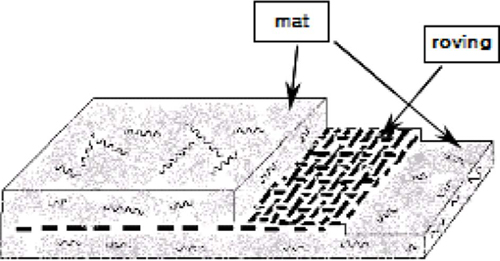
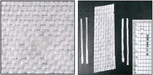
이제 폐기되는 FRP를 적극적으로 회수 처리하는 방법이 제시된바 있다(Hwang[2010], Nakagawa[1996]). 보다 환경 친화적인 재활용 방법으로 본 연구진은 섬유강화 콘크리트 제품으로의 환원을 연구하였다(Kim[2010]). 폐 FRP를 재활용하는 단계에서 FRP를 분쇄하지 않고 여러 층으로 되어 있는 FRP의 특성을 이용하는 것이다. FRP는 적층 구조로 이루어져 있다: 로빙층(roving layer)과 매트층(mat layer)(Fig. 1). 여러 가닥의 유리섬유가 바구니와 같은 짜임새로 엮어진 로빙층과 유리섬유가 엉킨 채로 깔리는 매트층이 번갈아 가며 수지로 접합되어 있어서 각 층을 수평적으로 박리할 수 있었으며, 박리된 로빙층을 폭 3 mm로 쪼개어 “F섬유”를 생산하였다(Fig. 2, Yoon[2007]). 이 때 F섬유의 규격은 그 용도에 맞게 조절할 수 있다.
폐 FRP 재활용섬유 강화 콘크리트(Recycled- Fiber Reinforced Concrete, RFRC)에 사용하기위해 F섬유에 대해 염기성 용액에서의 강도 실험을 수행하였다. 그 결과 층을 분리할 때 유리섬유에 잔존 하는 수지(약 25%)의 영향으로 순수한 유리섬유에 비해 강도를 유지하였다. 또한 F섬유를 2%까지 혼합하여 제조한 모르타르의 경우 알칼리 실리카 반응(ASR)에서는 오차 범위 내에서 변화가 없음이 관측되었고 휨강도에서는 수입산 섬유 강화재(P-54) 2%를 포한한 모르타르와 강도가 거의 같게 나왔으므로, 새로운 콘크리트 강화재로의 가능성을 보인 바 있다(Yoon[2007]).
본 연구에서는 섬유 강화 콘크리트(Fiber Reinforced Concrete, FRC)를 제작하여 물성을 측정하고 비교하고자 한다.
2. 실험 방법
2.1 실험 재료
폐 FRC 분리 장치로 매트층을 로빙층과 분리한 후 길이로 절단하여 F섬유를 생산하였다(Lee[2012]). 이 때 폭의 너비를 조절할 수 있으며, 실험을 위해 각각 3 mm와 1 mm의 폭을 갖는 F 섬유를 준비하였다. 이것을 3 cm의 길이로 절단하여 콘크리트 샘플 제작에 사용하였다.
설계기준강도 60 MPa에 대해 목표 슬럼프플로를 600±100 mm로 하고 공기량은 3.5±1.5%가 되도록 실험하였다.
기준으로 섬유를 혼입하지 않은 것과 0.1% PP(polypropylene) 섬유를 혼입한 것도 제작하여 비교하고자 하였다. RFRC 시편에는 섬유강화재(PP 또는 F섬유)와 고로슬래그분말은 30%, 폴리카르본산계 혼화재를 사용하였다(Table 1). F섬유 혼입율에 따른 강도 실험을 위해 F섬유(폭 3 mm)를 0, 0.5, 0.7, 1.0, 1.5%로 각각 혼입하였다(Table 1). F섬유의 폭에 따른 강도 실험을 위해 F섬유(폭 1 mm)를 0, 0.5, 0.7, 1.0, 1.5%로 각각 혼입하였다(Table 1).
콘크리트 공시체는 압축강도와 인장강도 실험은 φ100×200 mm 공시체로 제작하였으며, 휨강도 실험은 100×100×400 mm의 장방형 공시체로 제작하였다. 모든 공시체는 표준실험실에서 습윤양생하였으며 재령 7, 28, 56, 91일에서 압축강도, 인장강도, 휨강도를 각각 KS F 2405, KS F 2423 및 KS F 2408(3등분법 하중)에 의거하여 실시하였다.
2.2 실험 방법
설계기준강도를 60 MPa로 잡고, 슬럼프플로는 600±100 mm를 목표로 계획하였다. 공기량은 3.5±1.5%를 만족하도록 계획하여 실험하였다.
실험 변수로서 플레인 배합은 섬유를 혼입하지 않은 것으로, 섬유 혼입률은 폐 FRP의 경우 0.5%의 1수준, PP섬유의 혼입률은 0.1%의 1수준으로 총 3배치의 실험을 진행하는 것으로 실험계획 하였다. 이때, 고로슬래그미분말은 30%, 혼화제는 폴리카르본산계를 사용하였다.
콘크리트 시료를 제작한 후 7일, 28일, 56일, 91일 이후, 압축강도, 인장강도, 휨강도를 측정하였다.
3. 실험결과
Fig. 3~5는 Table 1의 방법으로 제작한 콘크리트의 (a) 압축강도, (b) 인장강도, (c) 휨강도의 측정 결과를 그래프로 나타낸 것이다. Fig. 3은 순수한 콘크리트, PP 섬유 0.1%를 포함한 FRC와 3 mm F섬유 0.1%를 포함한 FRC에 대한 강도 시험 결과이며, Fig. 4는 3 mm F섬유의 부피비를 달리한 FRC의 강도 시험 결과, Fig. 5는 1 mm F섬유의 부피비를 달리한 FRC의 강도 시험 결과이다.

Stress test by aging for the plain, PP (0.1%)-FRC, and F-fiber (0.5%) FRC: (a) compressive stress, (b) tensile stress, and (c) bending stress.

Stress test by aging for F-fiber (3 mm width) FRC depending on the mixing ratio of 0, 0.5, 0.7, 1.0, and 1.5%: (a) compressive stress,(b) tensile stress, and (c) bending stress.
4. 결론 및 고찰
앞의 실험 결과들을 재령 56일을 기준으로 강화 섬유를 첨가하지 않은 콘크리트 제품과 비교하여 강도 증가율을 계산하였다(Table 2).
Table 2의 분석에 보듯이 F섬유를 포함하여 생성한 콘크리트의 제품의 인장강도(19~30%)는 PP를 포함한 것의 인장강도(24%)와 견줄 수 있을 만큼 강하였다. 또한 휨강도(5~12%)는 PP(27%) 보다는 못하지만 상당한 수준의 강도 증가율을 보이고 있다. 그러나 압축강도는 -19~3%로 PP의 12% 보다 매우 나쁘며, 오히려 강화재를 넣지 않았을 때보다 더 낮은 성향을 보이고 있다. 이 결과는 F섬유의 용도를 결정할 때 중요한 물성이다.
이러한 현상은 콘크리트와 F섬유 간의 이질성으로 인해 압축의 힘이 주어질 때 콘크리트와 F섬유 표면의 인력이 깨져버린 것으로 설명된다.
합성수지의 경우는 섬유의 곡선으로 인해 압력이 주어졌을 때 탄성으로 그 압축력을 견딜 수 있었을 것으로 보이나, F섬유는 탄성이 없는 유리섬유들이므로 서로 근접한 압축영역이 반발하여 압축강도가 증가하지 않거나 오히려 감소한 것으로 해석된다.
또한, 3 mm의 폭을 갖는 F섬유 보다 1 mm 폭을 갖는 섬유를 사용하였을 때 9배 이상의 압축강도 감소를 보인 이유는, 두 가지 F 섬유를 같은 부피비로 첨가함에 따라 1 mm 폭의 F섬유의 개체수가 많아 콘크리트와 접촉하는 표면적이 많았을 것이며, 따라서 압축영역이 증대되고 압축강도가 감소된 것으로 본다.
결론적으로 F섬유의 물성 시험 결과 콘크리트 제품의 인장강도와 휨강도는 합성섬유에 못지않은 효과를 보이고 있으나, 압축강도는 현저히 떨어지는 것으로 나타났으며, 이 결과는 F섬유의 사용 용도를 다소 제한하고 있다. 그러나 인장강도와 휨강도의 증가는 가격과 환경적인 문제에서 보면 상당한 의미를 갖는 것이다. F섬유를 FRC에 사용한다면, 장점은 살리고 단점은 피해가며 재활용할 수 있을 것으로 보며, 그 활용도는 압축강도보다 인장강도과 휨강도가 주요 요인인 경우가 되겠다. 예를 들면, 도로 경계석이나 도로 중앙분리대 등을 들 수 있다.
Acknowledgments
본 연구는 홍익대학교 학술연구진흥비의 지원을 받아 수행되었음을 밝힌다.
References
- W.D Callister, D.G Rethwisch, Material Science and Engineering, ISV 8ed, John Wiley and Sons, New York, (2011), p227-228.
- E.H Hwang, J.K Jeon, “Preparation and Mechanical Properties of Bulk Molding Compound Composite Prepared using Recycled FRP Waste Powder”, App. Chem. Eng, (2010), 21(2), p217-233.
- T.S Hwang, J.W Park, C. H Lee, “A Study on the Preparation ana Mechanical Properties of Composites Reinforced FRP Waste and Rock-Crush Sludge”, Polymer(Korea), 24(6), p829-836.
- Y Kim, K.Y Yoon, S.H Lee, “Application Study of the reinforcing fiber produced from waste FRP on the High Strength Concrete”, Industrial Technique Final Report for Ministry of Environment, (2010).
- S.H Lee, Y Kim, K.Y Yoon, “A Study on the Chemical Treatments Suitable for the Simple Mechanical Manipulation During the Recycling Process of FRP Waste from Ships”, J. Kor. Soc. Marine Environment, (2009), 12(1), p55-59.
-
S.H Lee, J.K Lee, Y.J Kim, “A Study on the Chemical Pre-treatments Suitable for the Layer Differentiation of FRP Waste”, J. Kor. Soc. Mar. Env. Eng, (2011), 15(1), p47-53.
[https://doi.org/10.7846/JKOSMEE.2012.15.1.047]

-
S.H Lee, K.Y Yoon, “Developing Advanced Total Recycling Method of FRP Boats”, J. Kor. Soc. Mar. Env. & Ener, (2012), 16(1), p53-59.
[https://doi.org/10.7846/JKOSMEE.2013.16.1.53]

- Muneo Nakagawa, , “Basic Study on the Physical Properties of the concrete containing Waste FRP Powder”, Workshop Presentation Papers of Architectural Institute of Korea, (1996).
- K.Y Yoon, Y Kim, S.H Lee, “Recycle of the Glass Fiber Obtained from the Roving Cloth of FRP I: Study for the Physical Properties of Fiber-reinforced Mortar”, J. Kor. Soc. Mar. Env. Eng, (2007), 10(2), p102-106.


